- Here is the attendance
- Boss No.3
- Tonnam No.16
- Stang No.17
- Vivy No.18
- Tonkhao No.19
- Task
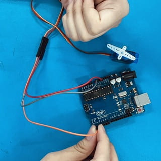
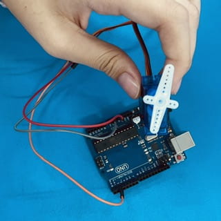
Moving four micro servo motor.
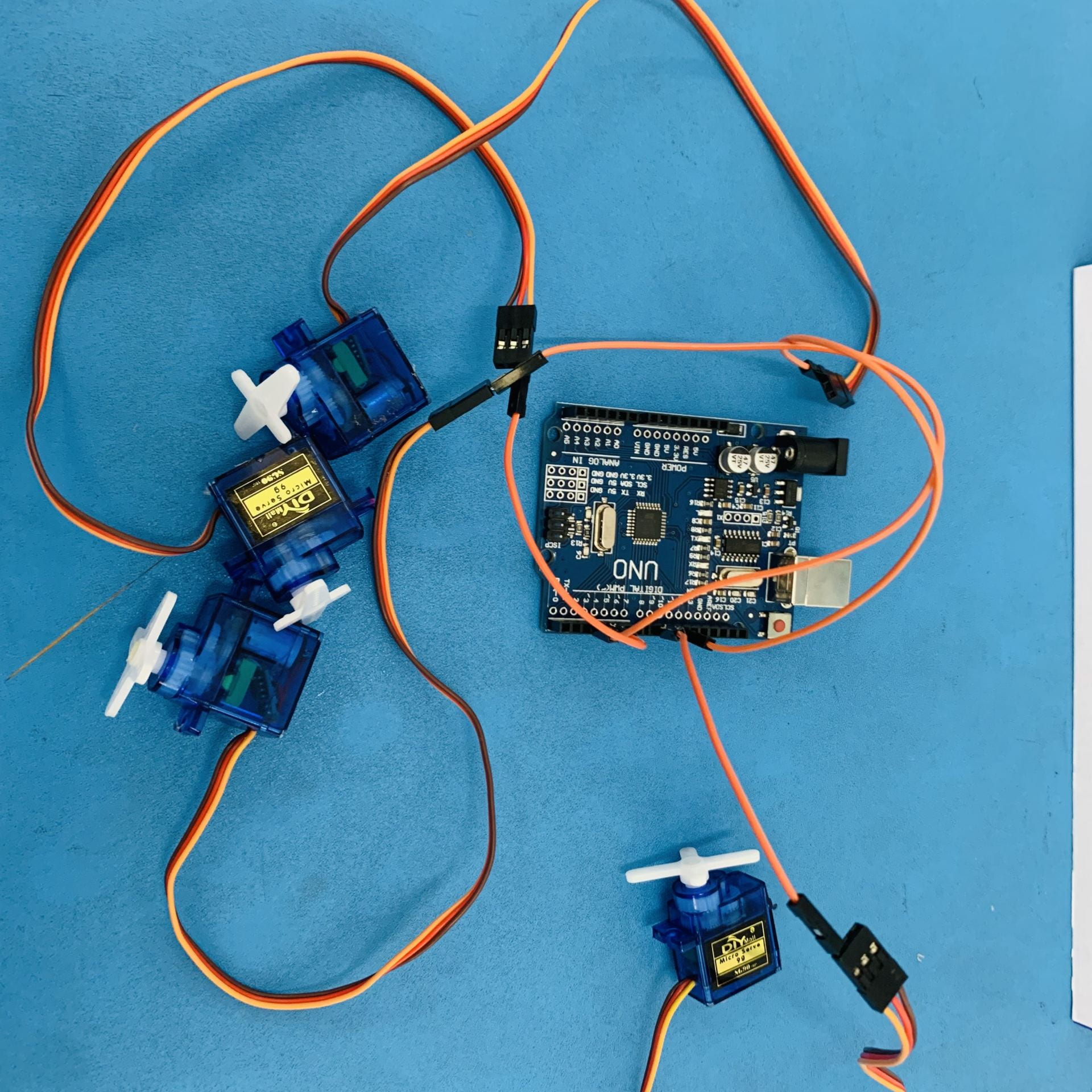
- Components
- Code
Servo rightfoot:
Servo rightthigh;
Servo leftfoot;
Servo leftthigh;
int pos;
void setup ()
rightfoot.attach (9). rightthigh.attach (5); leftfoot.attach (3); leftthigh.attach (11);
leftfoot.write (10); leftthigh.write (90);
rightthigh.write (100);
rightfoot.write (180);
void loop ()
delay (700);
leftfoot.write (20);
delay (300);
leftfoot.write (30);
delay (300);
leftfoot.write (40);
delay (300);
leftfoot.write (50);
delay (300);
leftfoot.write (60);
delay (700);
rightfoot.write (160);
delay (700);
rightfoot.write (150);
delay (700);
rightfoot.write (140);
delay (700);
rightfoot.write (130);
delay (1000);
leftfoot.write (35);
delay (500);
leftfoot.write (10);
rightfoot.write (140);
delay (500);
rightfoot.write (150);
delay (500);
rightfoot.write (160):
delay (500);
rightfoot.write (170);
delay (500);
rightfoot.write (180);
delay (700);
rightthigh.write (100);
delay (700);
rightfoot.write (150);
delay (300);
rightfoot.write (140);
delay (300);
right foot.write (130);
delay (300);
rightfoot.write (120);
delay (700);
leftfoot.write (20);
delay (300);
leftfoot.write (30);
delay (300);
leftfoot.write (40);
delay (300);
leftfoot.write (50);
delay (1200);
leftthigh.write (80);
delay (700);
leftthigh.write (90);
delay (700);
leftthigh.write (100);
delay (700);
right foot.write (150);
delay (700);
rightfoot.write (180);
delay (700);
leftfoot.write (40);
delay (300);
leftfoot.write (30);
delay (300);
delay (700);
rightthigh.write (90); leftfoot.write (20);
delay (700);
delay (300);
leftfoot.write (10);
rightthigh.write (80);
delay (700);
leftthigh.write (65);
delay (700);
rightthigh.write (70);
delay (700):
delay (300);
leftfoot.write (10);
delay (300);
leftthigh.write (90);
delay (300);
rightthigh.write (100);
delay (300);
right foot.write (180);
- Process
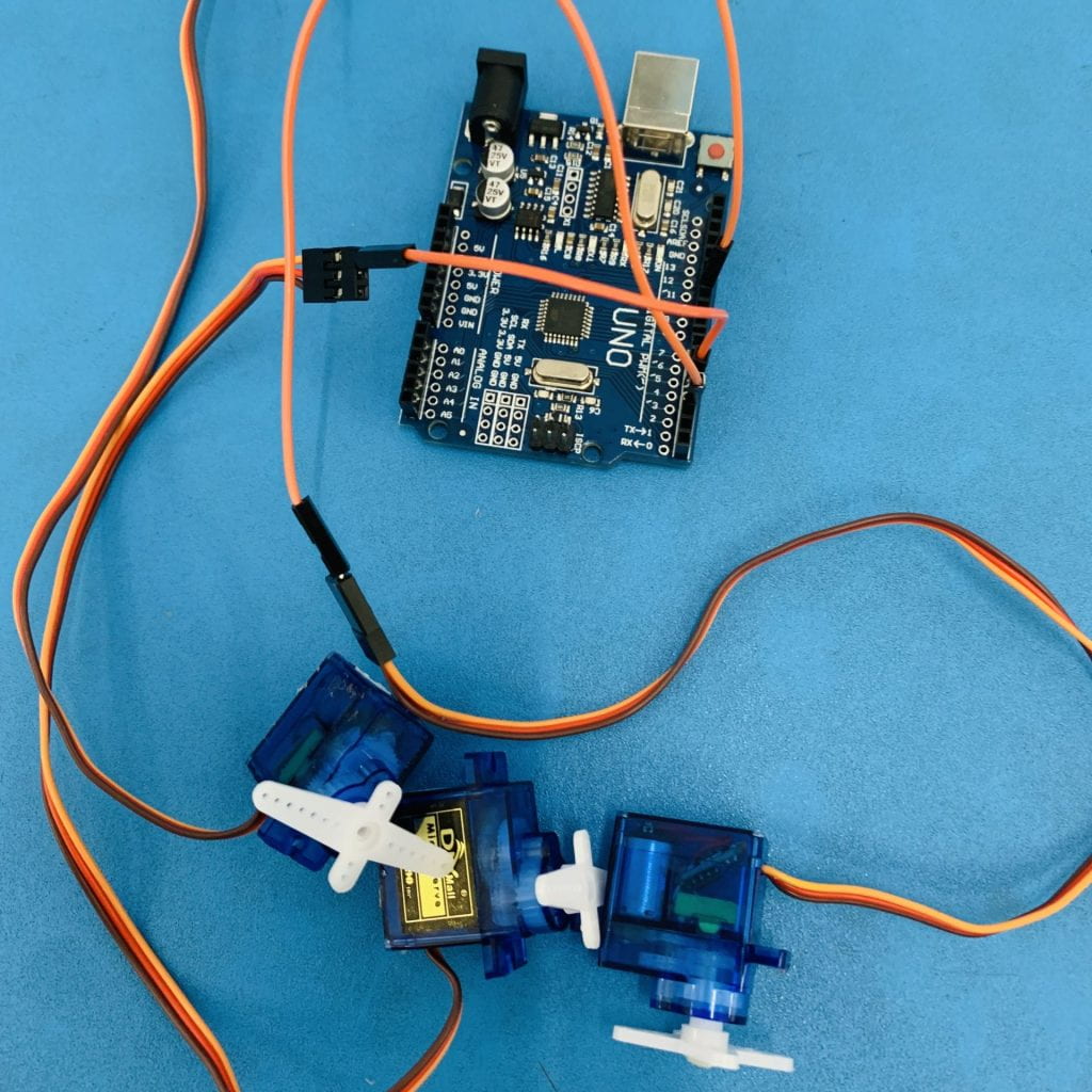
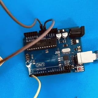
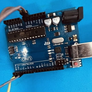
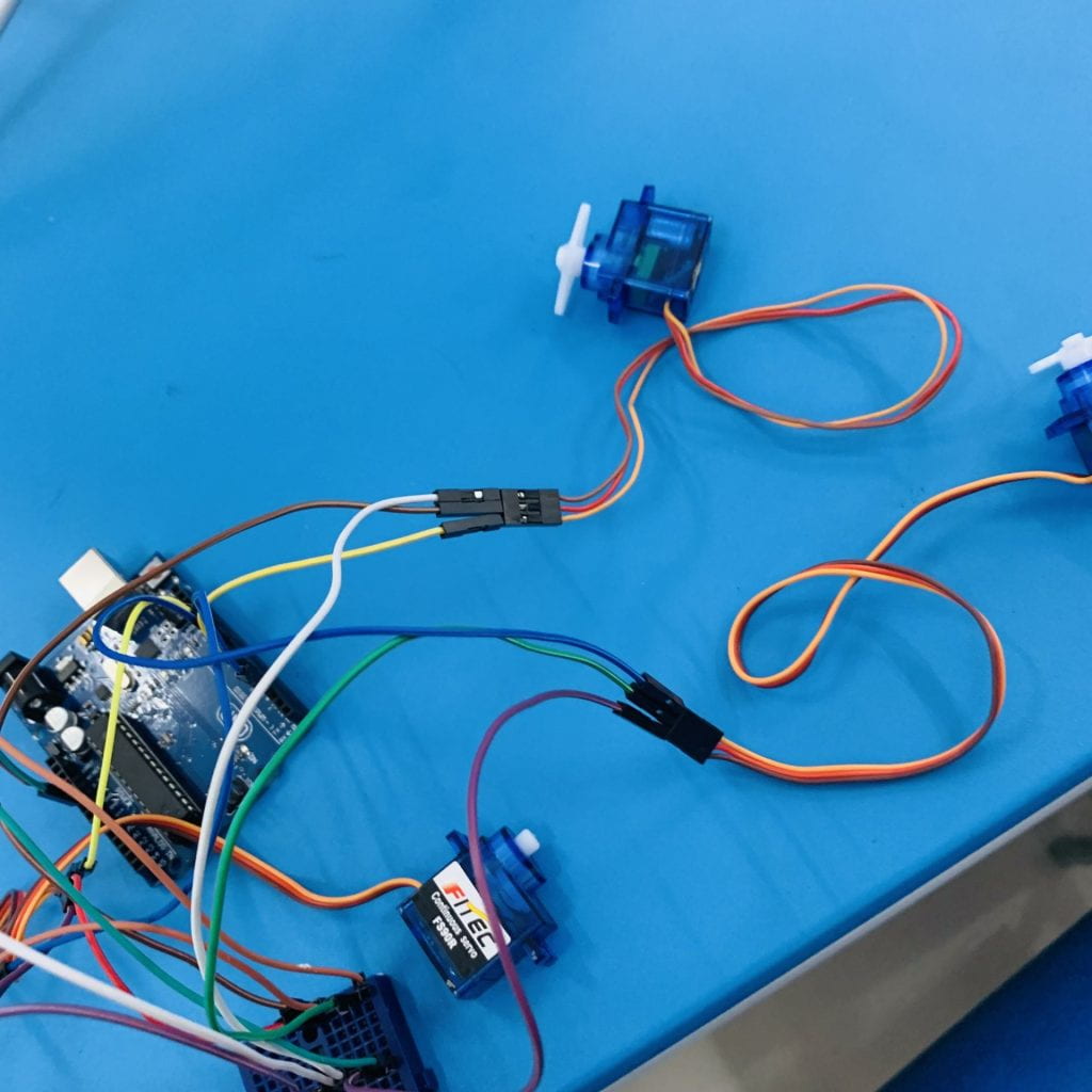
First : is take the yellow wire (signal wire) to connect to all 4 servos and connect to the digital pin ( where right-foot connects to 9 right right-thigh connects to 5 left-foot connects to 3 left-thigh connects to 11 )
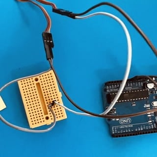
Second : is to bring the red power wire (power wire) to connect to all 4 servo and connect to the breadboard, all in the same row. Then take the jumper wire and connect the 5v to the breadboard. It must be in line with the red wire that connected to the servo.
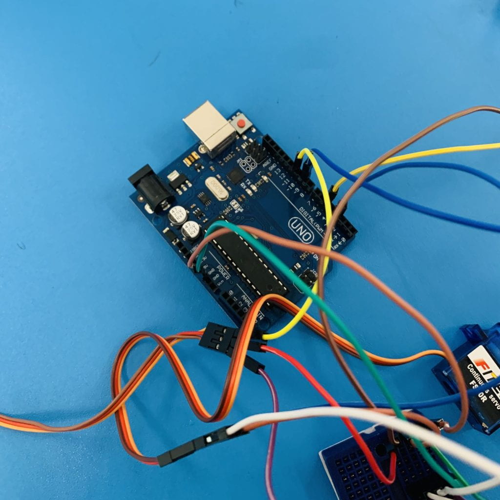
last step : do the same as step 4, but change to the brown wire (ground wire). Bring the wires to connect to the server and breadboard together by being in the same row. After that, bring the brown wire to connect the breadboard to the ground on the Arduino board.
- Output
Thank you
By Angle popop